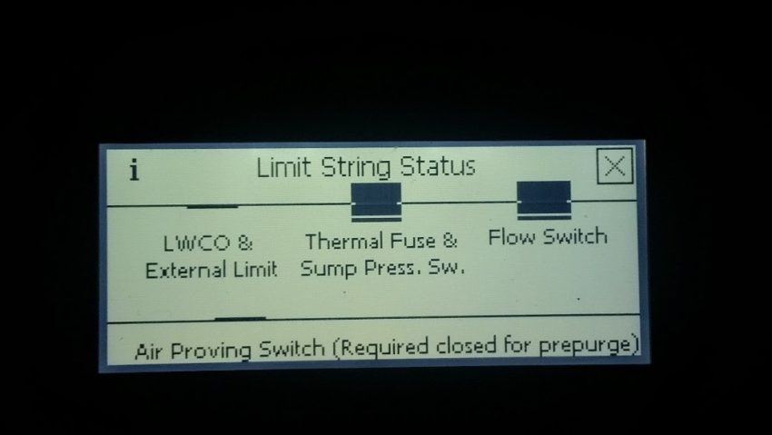
To access the “Limit String” screen from the home screen press the “Help” button followed by pressing the flashing “Fault Status” button. The next screen youn will have either “Soft Lockout” or “Hard Lockout” flashing along with the “Limit String Status”. Press the “Limit String Status” button and your next screen will have flashing boxes. The first box flashing is where the problem is. It may show a single limit or a group of limits. The rule here is when a limit is open all limits after that limit should be open. See picture below.

In this case either the thermal fuse or the sump pressure switch is open
Note: On the display these would be flashing
Which is the first box flashing?
Is the condensate trap flooded?
The air proving switch is connected to the gas valve with a rubber tube. When the display shows “Direct Ignition” the switch must see a negitive pressure for a short period. Remove the hose from the gas valve and verify the screw in the hose port is open at least 5 turns. Turn screw in all the way and back it out 5 turns. Did problem resolve?
Do not unplug the connector from the low voltage board. Test the bottom left hole for 24Vac. Is 24Vac present?
Remove cap on the bottom of the trap and clean trap. Repair condensate line for proper drainage. Error removed?
Touch status on the display, than the left arrow button 2 times To display “Pump Status” Is the boiler circulator displayed as on?
Make sure there is no demand on the boiler for heat or DHW. Turn down the thermostat(s) and IWH aquastat. Is the fan running continuously?
Control is in a low water condition. Check pressure and water level in the boiler vrifying water level is above the probe. If there is water replace the control.
Call Tech Services
Disconnect the molex connector on the thermal switch on top of the heat exchanger. Test 24 Vac on the grey wire stamped 43a. Is there 24Vac present?
Blead the air out of the heat exchanger from the blead port on the top right of the heat exchanger.
Unplug the harness from the flow switch. Meter the flow switch for continunity. Is the switch closed or open.
Press adjust 2 times, touch “Login”, touch zero’s in middle of the screen. Type in 86, press return key (bent arrow on the right) and press “Save”. Press “Adjust”. Press pump setup on the center left. Verify boiler pump is set for “any demand”.
Turn the boiler off and remove the wires from the air proving switch. Meter the terminals where the wires were for continunity. Is the switch closed?
Replace Jumper Plug.
Replace wiring Harness.
Verify the arrow on the flow switch is pointing down, away from the heat exchanger and parallel to the pipe. Installed properly?
Replace Harness
Change the circulator
Meter the Sage 2 control terminal marked J4-5 to “N” on the line voltage circuit board. Is there 120Vac present?
Defective switch, replace air proving switch
Are there CSD-1 controls installed on the External limit terminals or just the jumper.
Replace switch.
Remove and install properly. Switch installed properly?
Replace the wiring harness
Replace the Sage2 control
Replace wiring harness
Check voltage in and out of CSD-1 controls and reset or replace as needed.
Check jumper for continunity and good connection to terminals. Replace or repair as needed.
Call Tech Services

